
Contents of this Page:
1. The 720 Rotary Controller Rebuild
2. 720 Joystick Schematic Guide
3. Joystick Issues Summary
4. Joystick Disassembly & Maintenance Instructions
5. Spinning & Directional Issues
6. Joystick Variations/Revisions
7. My 720 Joystick History
1. The 720 Rotary Controller Rebuild
2. 720 Joystick Schematic Guide
3. Joystick Issues Summary
4. Joystick Disassembly & Maintenance Instructions
5. Spinning & Directional Issues
6. Joystick Variations/Revisions
7. My 720 Joystick History
720 Joystick Links:
720 Rotary Controller Rebuild - A great 720 joystick resource.
Arcadefixit.com - Sells replacement parts mentioned on this page.
720 MAME Joystick Project - Resource for MAME 720 Players.
720 Rotary Controller Rebuild - A great 720 joystick resource.
Arcadefixit.com - Sells replacement parts mentioned on this page.
720 MAME Joystick Project - Resource for MAME 720 Players.

Ataricade 720 Rotary Controller Rebuild Guide
First off, thanks to Francis Mariani, owner of the Ataricade His posting, 720 Rotary Controller Rebuild is an excellent source of information, and was my inspiration for adding this section to my site.
Enhanced
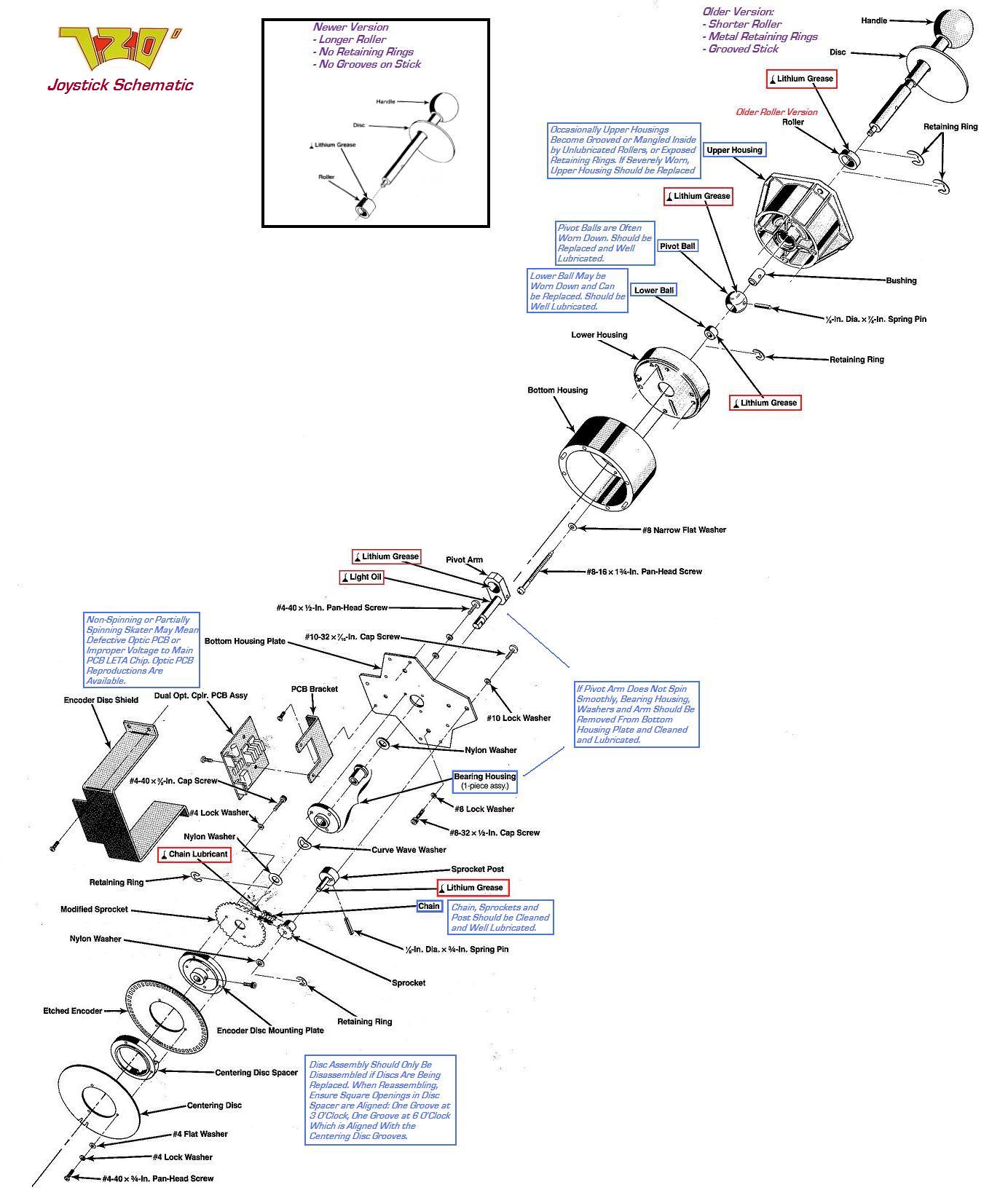
720 Joystick Schematic
720 Joystick Schematic
Refer to this schematic for joystick tips, and parts referenced on the rest of this page.
Joystick Issues Summary
A brief summary of common 720 joystick issues.
A brief summary of common 720 joystick issues.
** The key to a healthy 720 joystick is:
1. Careful maintenance and lubrication of the Roller, Pivot Ball and other components.
2. Proper assembly/orientation of the optic discs.
3. A working optic PCB.
** Wear of the roller creates secondary wear in the pivot ball, lower ball, upper housing and dust-cover disc.
** When you receive a new 720, disassemble the joystick, inspect the roller, pivot ball, lower ball, upper housing and dust cover for wear. Replace if worn. Lubricate the roller, pivot ball, lower ball, pivot arm hole and the sprocket post with white lithium grease. Lubricate the chain and pivot arm shaft with chain lubricant and oil. When reassembling, ensure the two notches in the centering disc rest in the black optic readers when the stick is pointed up/north (toward the side with the optic PCB)
** A defective Optic PCB may cause the skater to spin incorrectly, or not at all, and may have to be replaced.
Joystick Disassembly & Maintenance Instructions
** Some of this borrowed from the manual, some from my own experience - click the images for larger versions **
** Some of this borrowed from the manual, some from my own experience - click the images for larger versions **


Reach through the top coin door to release the spring-drawn latches under the control panel, then remove the screw from the front of the panel. Stand the control panel on its back edge by placing it in the wood slots under the control panel. From here you can remove the joystick from the panel, or you may disconnect the entire panel by disconnecting the rotary control harness plug and the two PCB harness connectors. Remove the 4 hex nuts holding the joystick assembly to the control panel.


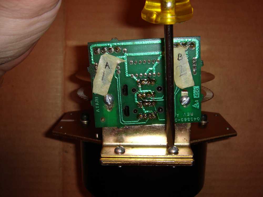
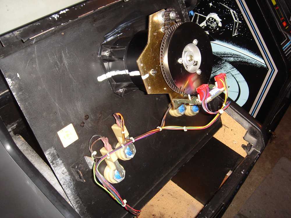
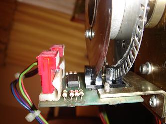
Once the joystick assembly is separate, start by removing the Encoder Disc Shield (Missing from my joystick, but included in Franciss 720 Rotary Controller Rebuild Post in (this picture) Next remove the Optic PCB Assembly by removing the two connecting screws. During reassembly the PCB Brackets position can be adjusted to properly place the discs between the black optic readers before tightening these screws.

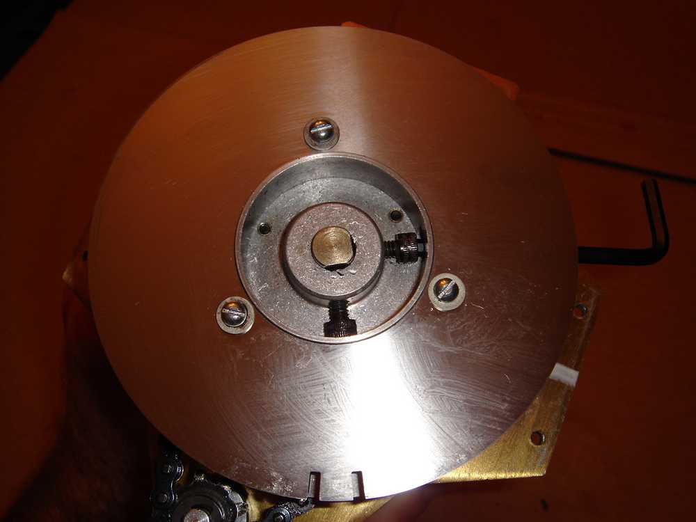

Next remove the small Sprocket Assembly from the Bottom Housing Plate. If the sprocket does not spin freely, remove the small retaining ring and nylon washer, and clean and lubricate these parts. Next remove the two encoder discs by loosening the two allen set screws. The discs need not be further disassembled unless you are replacing them. If the discs are fully disassembled, ensure they are properly aligned when reassembling. The Etched Encoder Disc orientation does not matter, but there are three possible orientations of the Centering Disc relative to the openings in the Disc Spacer (which are for access to the allen set screws). When the Disc Spacer is held with openings at 3 and 6 oclock (as shown in the right picture above), the grooves in the Centering Disc must be lined up with the 6 oclock opening (aimed down) as shown.

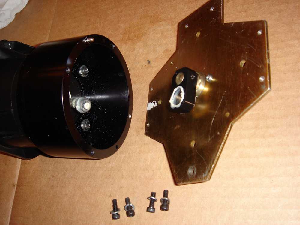
Once the bicycle chain is free it will most likely need to be cleaned and lubricated with a good quality chain lubricant. Next remove the 4 allen screws and separate the Bottom Housing Plate from the black circular Bottom Housing.


Inspect the Pivot Arm and ensure it spins smoothly and very freely. If not, remove the retaining ring, washers, and bearing assembly in which the Pivot Arm spins. Clean and lubricate these components.
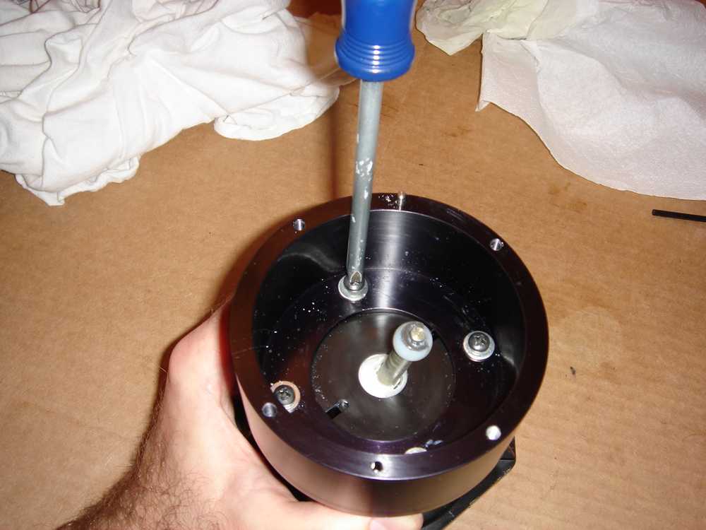

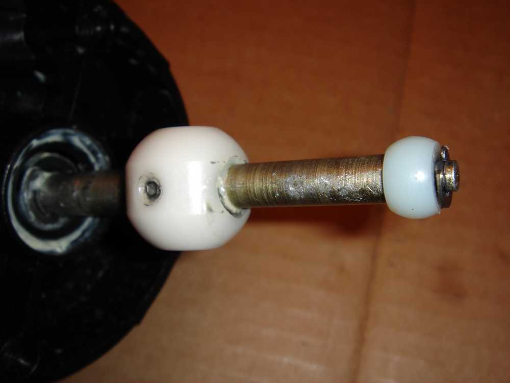
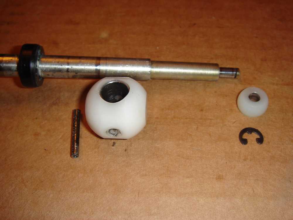
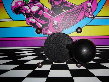
Remove the 4 long screws and separate the Bottom Housing and Lower Housing from the Upper Housing exposing the Pivot Ball. Remove the small retaining ring and Lower Ball from the joystick. If the Lower Ball is worn it should be replaced, and should be well lubricated when reassembled. Next, place the stick in a vice and tap a punch through the Pivot Ball to remove the Spring Pin and slide the Pivot Ball off the Joystick. If the Roller is at all worn, the Pivot Ball will almost certainly worn and need to be replaced. Remove the metal bushing from inside the ball and slide it into your replacement. Ensure the Pivot Ball is well lubricated when reassembling. Next remove the roller. It may be worn and need to be replaced. If you have a newer joystick version, you may just slide your roller off the stick. If you have the older version, you will have to remove two retaining rings before sliding the small roller off. I recommend replacing this roller with the newer, longer version. The old-version metal joystick with grooves for the retaining rings can be used with the newer roller. See further down on this page for more info on the different roller versions. Either Roller version should be well lubricated when reassembled.

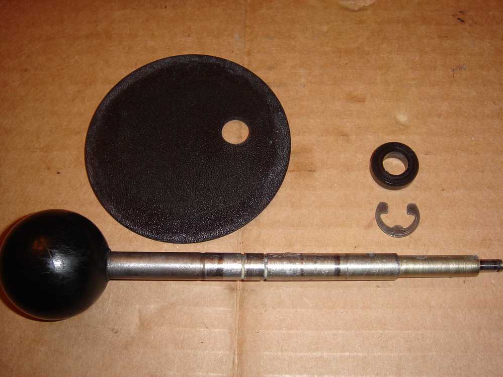

You should now be able to slide the metal joystick out of the Upper Housing and remove the dust cover Disc. If the roller had been worn at all, there is a good chance the Disc has been worn down smaller than intended and should be replaced. Inspect the inside of the Upper Housing. If the roller has become worn and/or the stick was not properly maintained and lubricated, the inside of the Upper Housing may have had grooves worn into it. If these grooves are severe enough, the roller will contact the Upper Housing at a point further out from the center of the joystick assembly than intended. This causes undo wear on the Pivot Ball and Lower Ball. A severely worn Upper Housing should be replaced. In the picture above you can see an Upper Housing that has been grooved by an old-version small roller that wore down enough for the metal retaining rings to grind against the housing.
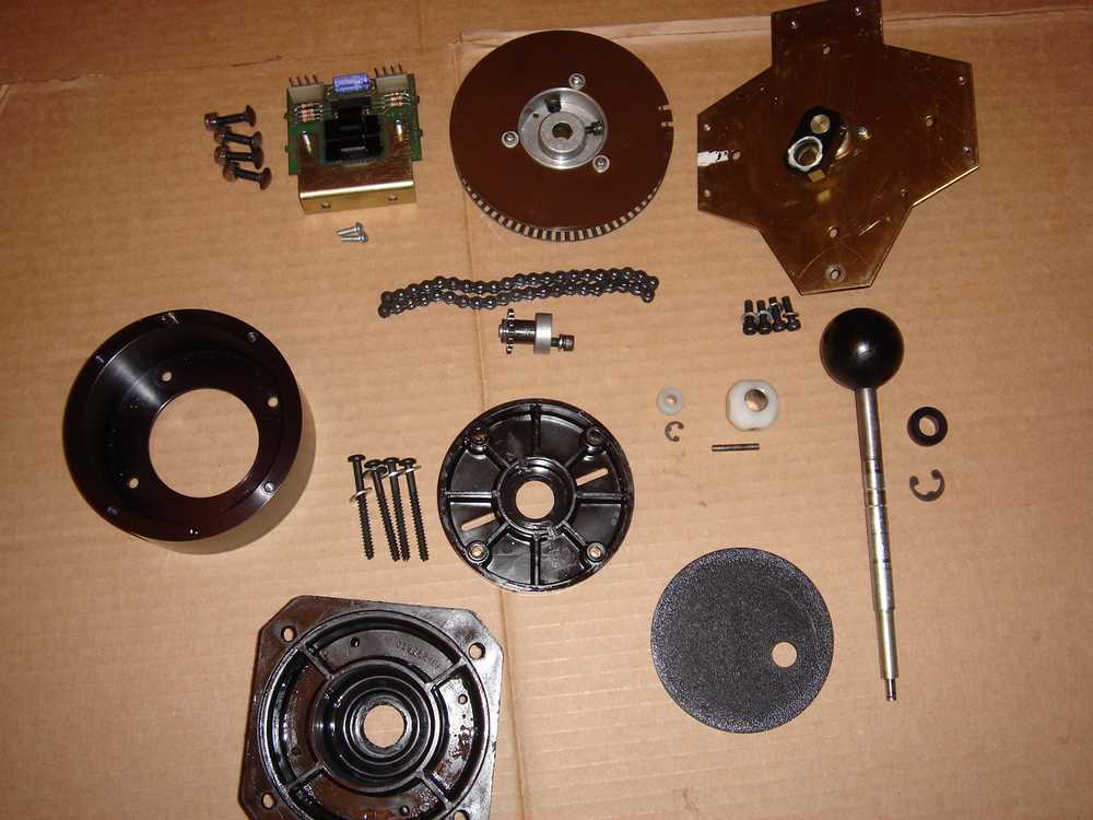
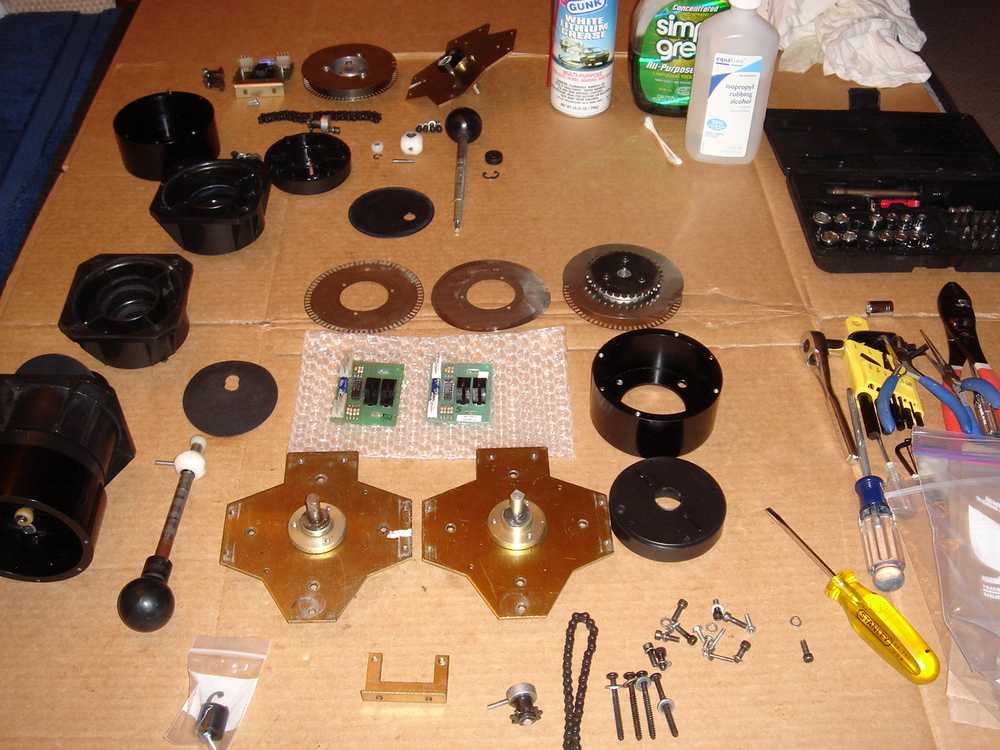
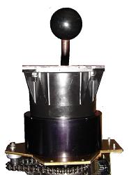
These steps should be enough disassembly to take care of most mechanical problems with the joystick. Reverse the above steps to reassemble. Further problems related to the electronics are handled in the next section. To the right is the disassembled stick from the above example; further over is spare parts Ive amassed over the years.
Spinning & Directional Issues
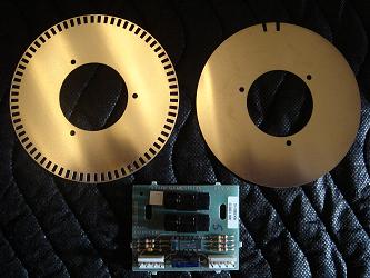
Optic Discs: The skaters spin speed and direction are governed by the optic discs passing through the optic readers on the optic PCB. The Etched Encoder Disc (Left in the first picture above) manages the distance, speed and direction the skater spins. The Centering Disc (Right in the first picture above) continuously calibrates the skater, ensuring he is pointed in the correct direction relative to the stick.
Spinning Problems: A non-spinning skater or a skater that spins partially or in random directions is most likely due to a defective Optic PCB. Various newsgroup and message board postings deal with PCB repair and replacement of the black optic readers, but this is beyond my experience. Fortunately, NOS or reproduction Optic PCBs and Optic Encoders are usually available. There is also a known issue with joystick input failing when the +5 voltage to the LETA chip on the main PCB is not correct. This issue is addressed in the KLOV Message Board Post: 720 Controller Board.
Skater Direction: An incorrectly assembled joystick, specifically the orientation of the optic discs, can cause the skater to point to either 4 oclock or 8 oclock when the joystick is aimed up (12 oclock). See this portion of the Joystick Maintenance section of this page.
The "Fluttering" Skater: Occasionally players will noticed that as they spin in the air, the skater will sometimes appear to flutter instead of spinning smoothly. It may appear that the skater is very quickly pointing in many different directions, rather than progressing through a single spin. Upon landing, points will not be given for one revolution. This may be due to bent or warped optic discs, as was the case with my joystick at one point. The flutter can also be due to playing technique, and can be eliminated with an adjustment to spin speed. To test this, enter Test Mode and cycle to the Joystick test screen on which you spin the stick one full revolution to fill in a circle of small blocks.
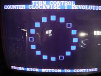
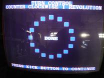
When the stick is spun too fast, some of the blocks will not be filled in, which equates to a fluttering skater, and an incomplete (no points) spin.
When the stick is spun at the correct speed, all of the blocks will be filled in, and proper credit given for the spin.
Joystick Variations / Revisions
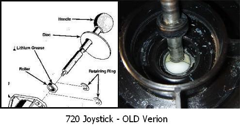
Its important to note that there are two drastically different joystick versions that were released for the 720. The key difference is in the contact point between the joystick bar and the upper housing.
The early version has a small roller, held onto a groove in the upper joystick bar by two metal retaining rings. Over time this design was proven flawed. Through excessive use, and/or improper maintenance (lubrication) the small roller piece would begin to wear down as it rubbed against the inside of the upper housing. The rollers sides are straight (perpendicular to the joystick shaft), but the stick is at an angle where it contacts the upper housing, meaning that only the upper corner of the small roller is making contact with the upper housing. This small area of contact will almost certainly become worn down until the metal retaining ring becomes the widest point, and the new point of contact with the upper housing. This would begin to carve out a groove in the upper housing, which allowed the circle the stick spins in to become wider and wider. This put undo stress on several components that were never designed help hold the size of the outside edge of the spinning circle the joystick makes. The result was faster wear of the upper dust cover, the pivot ball and the lower ball. Ive found that some operators would see that a groove had been worn in their upper housing by the old style roller, and would attempt to fix it by sanding the inside of the upper housing flat. Unfortunately this only made the joysticks spinning circle even larger and perpetuated wear on other components.
Any time you see a joystick with a worn dust cover (both the outside edges or the small hole the joystick fits through would become worn) the problem of the joysticks spinning circle becoming too large has begun to occur.
If you have this style of joystick, it is important to stop any grooves from being created in the upper housing. I used the old version of the joystick for many years after rebuilding one from NOS parts. A few steps I took to mitigate the wear are:
1. When I noticed the contact point of the roller beginning to wear, I flipped it over on the stick, so that the untouched bottom portion became the new contact point.
2. I removed the top metal retaining ring, relying on gravity to keep the roller down against the lower ring. This eliminates the risk of metal ever grinding against the upper housing.
3. Very regular inspection and lubrication of the small roller .
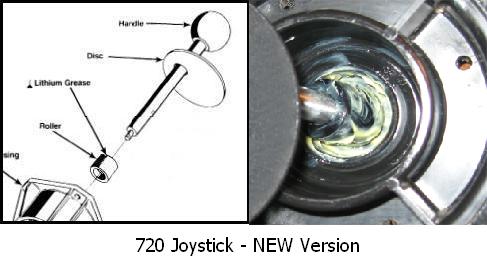
The newer, revised and improved version uses a much longer roller piece that is the correct size to fit directly on the main thickness of the metal shaft. This is design uses no metal retaining rings, which protects the upper housing from the damage described above.
The new joystick revision also included a new metal stick which is the same thickness, but does not have the grooves for the roller retaining rings.
In conclusion, an ideal stick will use the longer updated roller. It is possible to use the older style, but lubrication of the smaller roller should be carefully maintained.
2. I removed the top metal retaining ring, relying on gravity to keep the roller down against the lower ring. This eliminates the risk of metal ever grinding against the upper housing.
3. Very regular inspection and lubrication of the small roller .
The newer, revised and improved version uses a much longer roller piece that is the correct size to fit directly on the main thickness of the metal shaft. This is design uses no metal retaining rings, which protects the upper housing from the damage described above.
The new joystick revision also included a new metal stick which is the same thickness, but does not have the grooves for the roller retaining rings.
In conclusion, an ideal stick will use the longer updated roller. It is possible to use the older style, but lubrication of the smaller roller should be carefully maintained.
Jeff's 720 Joystick History
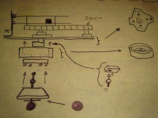
When I purchased my 720 in late 2001, the joystick worked completely, but was slightly out of position and extremely hard to turn. It made an awful grinding sound as it spun. Before beginning my cosmetic restoration, I wanted to get some games in, so I started with the joystick repair. I pulled the control panel off, set it on the workbench, and started taking the assembly apart. I had no manual or schematic, and absolutely no experience with anything related to arcade games. I carefully took each piece off, and made notes and drew pictures so Id remember how everything fit together. I cleaned and lubricated each piece and put the entire thing back together.
When I first fired it up, the stick spun much more smoothly, but my skater faced Southwest when the stick was pointed north. I pulled the entire thing apart, reoriented the discs, and I was back in business. The stick still grinded a bit, but the game was playable.
A few weeks later I purchased a second, incomplete joystick assembly off of Ebay, plus a few NOS parts that became available. When everything arrived I once again pulled the entire joystick apart, and did the same to my second joystick assembly. I then compared each piece and made the best single assembly I could, out of my parts. I was lucky to get a NOS upper assembly piece, as mine had deep grooves in it, and had been partially sanded down. When everything was together, the joystick spun very smoothly.
Over the next 4 or 5 years my roommate and I played very regularly, and I did not keep up on lubrication of the joystick. The only joystick maintenance I performed was changing out my optic reader PCBs to attempt to alleviate fluttering (see below), and replacing my optic discs, which were badly bent and warped. When I finally pulled the joystick apart I noticed that my small roller piece had worn down and begun to wear grooves in my upper assembly. I made a few small adjustments to the roller and re-lubricated, and the stick was again very smooth.
A few months later I obtained some extra parts, including a new, reproduction updated longer version roller. I then converted my joystick to the newer, long-roller version, and noticed that the spinning felt even smoother, and somehow more solid. Im certain I now have the joystick performance that the original designers intended for a 720 rolling off of the assembly line.
A few months later I obtained some extra parts, including a new, reproduction updated longer version roller. I then converted my joystick to the newer, long-roller version, and noticed that the spinning felt even smoother, and somehow more solid. Im certain I now have the joystick performance that the original designers intended for a 720 rolling off of the assembly line.
I hope this page is helpful. Please don't hesitate to contact me with any further questions.


All content © 2009-2015, all rights reserved.